

Shearing, also known as cutting, is the initial process in the manufacture of three-piece cans and a crucial step in the production of printed tinplate cans. Its purpose is to cut pre-formed multi-mode printed and coated sheet metal into independently sized single-mode pieces according to specified dimensional requirements, meeting the needs of the subsequent resistance welding process. Due to the high precision requirements of the resistance welding machine for sheet metal cutting, circular shearing technology is commonly employed. Traditional manual cutting is no longer used, and modern double-disc shearing machines are preferred. Advanced shearing machines can quickly adjust the dimensions of the sheet metal by inputting the required commands into the software, allowing for efficient cutting. However, replacing traditional circular shearing machines may involve a transitional process. Currently, the mainstream shearing equipment used domestically is produced in Italy, Taiwan, and other active regions in the domestic light industry, adapting to the growing needs of the can-making industry.
Components of Shearing Equipment:
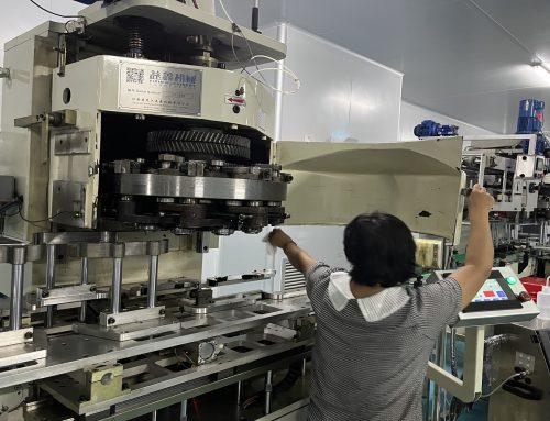
Shearing equipment is composed of an automatic tinplate feeder, bidirectional double-disc shearing machine, and a mechanical arm device that is compatible with automatic receiving, conveying, and feeding, as well as resistance welding machines. The control system includes an electrical control system, safety protection system, mechanical positioning synchronous transmission system, and bidirectional double-disc shearing mechanism (see the appendix: disc blade grinding device).
The term “bidirectional shearing” refers to completing the longitudinal segmentation of the can body circumference as the first step, and completing the transverse segmentation of the can body height as the second step (see Figure 3-30). To meet the layout requirements of different can types, a certain number of disc blades should be equipped. Shearing machines generally use seven pairs for the first step and nine pairs for the second step, which can meet the production needs. In the example, the sheet metal is first cut into strips (e.g., one, two, three, four, five) by the first set of rollers shown in Figure 3-31, and then each strip is further cut into individual single-mode pieces (e.g., 1, 2, 3, 4, 5, 6, 7) by the second set of rollers shown in Figure 3-32.
Shearing Machine Workflow:
The shearing machine control process involves sheet metal suction feeding, dual-sheet sensing, dual-sheet picking, conveying and sensing counting, positioning, first-step shearing, reversing conveyance, repositioning, second-step shearing, and controlled material collection.
The feeding rack of the shearing machine is shown in Figure 3-33.
Quality Inspection of Sheared Products:
Key inspection items for sheared products include width, length, right angle degree, arc-shaped plates (also known as sickle bends), burrs, and the appearance of welding reserved edges and printed surfaces. The minimum width requirement for waste edge material is 1.0 mm (Note: Too small waste edge material can cause blade entanglement, hindering normal production). Measurements for the above items can be done using a flat plate gauge and a vernier caliper, with error requirements following corresponding national standards or enterprise standards suitable for actual production needs.
For instructions on grinding the disc blades, please refer to the relevant equipment manual. The structure of the upper and lower disc blades is shown in Figure 3-34.
Currently, most high-speed welding machines use robotic arms for automatic material loading. However, if manual operation is required to feed the welding machine, attention must be paid to prevent contamination of the can body plates and to ensure that cut plates are used in a timely manner to prevent rusting of the cut edges, which could affect welding quality.
Common Issues and Troubleshooting in Shearing:
1. Adjusting the spacing between disc blades for different product specifications: Loosen the blade seat bolts, adjust the position of each set of blades according to the required cutting size, and lock the blade seat to secure the blade position.
2. When the sheet metal specifications change, adjust the corresponding positioning side rule position and the magnetic separating device position on the feeding rack to meet normal production requirements.
3. Deviation in width and height: Adjust the spacing between each set of blades to achieve the predetermined requirements. The typical deviation requirement is L ± 0.05 mm for the can body circumference and H ± 0.10 mm for the can body height.
4. Excessive burrs: Adjust the gap between the upper and lower blades and sharpen the blade edges. The gap between the upper and lower blades typically requires 0.02–0.03 mm. The blade edges should be smooth, continuous, and without notches. The burr requirement is ≤ 0.15Tb (Tb is the thickness of the can body tinplate). Pay attention to maintaining the correct orientation of the burrs, with the circular direction (burrs should be on the inner side of the can body overlap) and the can height direction (burrs should avoid being on the inner side of the can body where the aluminum cover is located). This helps ensure welding seam quality and the sealing of the aluminum bottom/cover double-folded edge.
5. Excessive right-angle deviation (diagonal cut): This may be caused by the non-vertical positioning edge with the blade axis or uneven forward and backward pushing force between the double push claws for feeding. Check whether the front and rear widths of the waste edge material are unequal through visual inspection, or check for unevenness in the diagonal by comparing the positive and negative sides on both sides. Alternatively, use a right-angle gauge to accurately measure the deviation value. The right-angle deviation typically requires that the deviation between the measured cutting edge and the baseline in the vertical direction of the fixed edge be ≤ 0.10 mm.
6. Unequal deviation in welding reserved edges on the left and right: Adjust the position of the positioning edge reasonably and allocate the width of the waste edge material on both sides. Additionally, the tightness of the pressure of the pressing edge should be adjusted to be moderate to avoid blade expansion or loss of positioning effectiveness. It must be emphasized that ensuring the quality of the sheared can body plates is essential to guarantee welding seam quality.
More: Key Features of Advanced High-Speed and Automated Tinplate Printing Equipment
